Floating Ball Valves: Design, Working Mechanism, and Advantages for Fluid Control
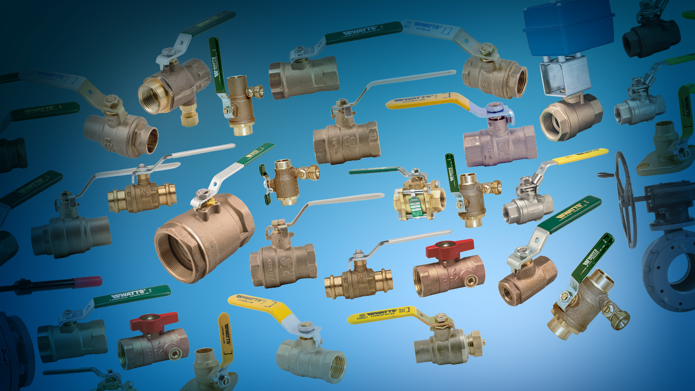
Floating ball valves are widely used in industrial piping systems because of their simple construction, dependable shutoff performance, and quick quarter-turn operation. They are designed to control the movement of liquids and gases by rotating a spherical closure element inside the valve body. Unlike trunnion-mounted designs, a floating ball is not fixed to a lower mechanical support. Instead, it is held in position by the valve seats and moves slightly under fluid pressure to create a tight seal.
These valves are commonly found in oil and gas facilities, chemical processing plants, water systems, and general industrial applications. Understanding their construction, operating mechanism, and performance characteristics helps engineers determine whether this design is suitable for a particular service. When reviewing available Floating Ball Valve options, it is important to consider pressure ratings, materials, seat design, and process conditions rather than relying on valve size alone.
What Is a Floating Ball Valve?
A floating ball valve is a quarter-turn valve that uses a spherical ball with a drilled passage to start, stop, or control fluid flow. The ball is not mechanically anchored by a trunnion. It is supported by two sealing seats positioned on either side of the ball.
When the valve is open, the ball’s bore aligns with the pipeline, allowing fluid to pass through. When the handle or actuator rotates the ball by approximately 90 degrees, the solid portion of the ball blocks the passage and stops flow.
The floating design allows the ball to shift slightly downstream when exposed to fluid pressure. This movement presses the ball against the downstream seat, helping establish a seal. The effectiveness of this sealing arrangement depends on the valve’s design, seat materials, pressure conditions, and manufacturing tolerances.
Main Components of a Floating Ball Valve
A floating ball valve contains several components that work together to provide reliable operation and sealing.
1. Valve Body
The valve body forms the main pressure-containing structure. It houses the ball, seats, stem, and other internal components. Depending on the design, the body may be manufactured from stainless steel, carbon steel, brass, or other compatible materials.
Body construction may be one-piece, two-piece, or three-piece. The selected configuration affects maintenance access, assembly, and installation requirements.
2. Floating Ball
The ball is a spherical closure element with a central opening. It rotates to align or block the flow passage. Unlike a trunnion-mounted ball, it is supported primarily by the seats and can move slightly under pressure.
The ball’s material and surface finish influence corrosion resistance, wear, and sealing performance.
3. Seats
Seats are positioned around the ball to provide sealing between the ball and valve body. Common seat materials include PTFE and other engineered polymers, although specialized designs may use different materials.
Seat selection depends on fluid compatibility, temperature, pressure, and operating frequency. The seats must maintain sufficient sealing performance without excessive friction or premature wear.
4. Stem
The stem connects the ball to the operating handle or actuator. It transfers rotational movement to the ball and is designed to withstand the mechanical loads generated during operation.
Stem sealing arrangements, including packing or other sealing elements, help prevent external leakage.
5. Stem Packing and Seals
Packing and seals prevent fluid from escaping around the stem and through body joints. Their material and arrangement must be suitable for the process medium and operating conditions.
Regular inspection can help identify deterioration, leakage, or excessive friction.
6. Handle or Actuator
A manual handle is commonly used for smaller valves and applications that do not require automation. Larger or automated installations may use pneumatic, electric, or hydraulic actuators.
The actuator must provide enough torque to operate the valve under the expected pressure and service conditions.
How Does a Floating Ball Valve Work?
The operating principle is based on the rotation of the ball and the pressure-assisted movement that helps establish a downstream seal.
Open Position
When the valve is fully open, the ball’s internal bore is aligned with the pipeline. Fluid passes through the valve with a relatively direct flow path.
In a full-port design, the bore is approximately the same diameter as the connected pipeline, helping reduce flow restriction.
Closed Position
When the handle or actuator rotates the ball approximately 90 degrees, the bore moves perpendicular to the direction of flow. The solid surface of the ball blocks the passage, stopping fluid movement.
The upstream pressure pushes the floating ball toward the downstream seat. This contact creates the sealing force that helps prevent fluid from passing through the closed valve.
Intermediate Position
The ball can also be positioned between fully open and fully closed. However, standard floating ball valves are generally intended for on-off service rather than continuous throttling.
Keeping a conventional ball valve partially open under certain operating conditions may cause localized turbulence, seat erosion, vibration, or premature wear. Specialized control designs should be considered when accurate flow regulation is required.
Types of Floating Ball Valves
Floating ball valves are available in several configurations to meet different installation and operating requirements.
1. One-Piece Floating Ball Valves
One-piece valves have a compact body construction. They are often used in applications where simple installation and economical design are priorities.
Because the body is generally not designed for extensive internal servicing, maintenance options may be more limited than with other configurations.
2. Two-Piece Floating Ball Valves
Two-piece designs consist of two main body sections joined together. They are commonly used in industrial piping because they offer a balance between compact construction and practical assembly.
The body joint must be properly designed and sealed to maintain pressure integrity.
3. Three-Piece Floating Ball Valves
Three-piece valves have a central body section connected to two end pieces. This configuration can allow the central section to be removed for inspection or maintenance without disconnecting the entire valve from the pipeline, depending on the manufacturer’s design and installation requirements.
They are often selected where serviceability is an important consideration.
4. Full-Port Floating Ball Valves
A full-port valve has a ball bore that closely matches the internal diameter of the connected pipeline. This design minimizes flow restriction and can be useful in systems where pressure loss and passage size are important.
5. Reduced-Port Floating Ball Valves
Reduced-port valves have a smaller internal bore than the pipeline connection. They are generally more compact and may be suitable where some flow restriction is acceptable and system calculations confirm their suitability.
Advantages of Floating Ball Valves
Floating ball valves offer several practical advantages in industrial fluid control.
Reliable Shutoff Performance
The pressure-assisted sealing mechanism helps the ball press against the downstream seat. When the valve is correctly selected and maintained, this arrangement can provide effective shutoff.
Actual leakage performance depends on seat design, material condition, pressure differential, and applicable testing requirements.
Quick Quarter-Turn Operation
The valve typically moves between open and closed positions through a 90-degree rotation. This allows faster operation than many multi-turn valve designs.
Quick operation is useful in applications where rapid isolation is required, although system designers must consider potential pressure surges caused by sudden closure.
Compact Construction
Floating ball valves generally have a straightforward internal arrangement. Their compact construction makes them suitable for a wide range of industrial piping installations.
Low Flow Resistance
Many floating ball valves provide a relatively direct flow path when fully open. Full-port designs can reduce pressure loss compared with more restrictive valve configurations.
Versatile Material Options
Manufacturers offer floating ball valves in different body, ball, stem, and seat materials. This allows selection for a variety of fluids, temperatures, and industrial environments.
Material compatibility must be checked for every wetted component, not just the valve body.
Simple Operation
Manual floating ball valves are generally easy to operate and do not require multiple turns to reach the open or closed position. Automated versions can also be integrated into process control systems.
Common Applications of Floating Ball Valves
Floating ball valves are used in many industries where reliable isolation and straightforward operation are required.
Oil and Gas Industry
They can be used in suitable pipeline sections, fuel systems, processing equipment, and utility services. Pressure ratings, fire-safe requirements, emissions performance, and material compatibility must be verified for the specific application.
Chemical Processing
Chemical plants use floating ball valves to isolate and control compatible process fluids. Selecting suitable body alloys, seat materials, and stem seals is essential when handling corrosive or reactive substances.
Water Treatment Systems
These valves may be installed in water distribution, filtration, pumping, and treatment systems. The material selection should account for water chemistry, treatment additives, and operating pressure.
Manufacturing Facilities
Industrial manufacturing systems use floating ball valves in compressed air lines, cooling circuits, utility piping, and equipment connections.
HVAC and Building Services
Depending on pressure, temperature, and fluid requirements, floating ball valves can be used for isolation in heating, cooling, and other building utility systems.
Floating Ball Valve vs. Trunnion-Mounted Ball Valve
Floating and trunnion-mounted ball valves use similar quarter-turn operating principles, but their support arrangements and pressure capabilities differ.
| Feature | Floating Ball Valve | Trunnion-Mounted Ball Valve |
|---|---|---|
| Ball support | Supported by seats | Mechanically supported by trunnions |
| Ball movement | Moves slightly under pressure | Limited movement due to fixed support |
| Sealing mechanism | Pressure pushes ball against downstream seat | Spring-loaded or pressure-assisted seat designs may be used |
| Typical pressure applications | Common in lower and medium pressure ranges, depending on design | Often selected for larger sizes and higher pressure services |
| Operating torque | Can increase with pressure differential | Often lower for comparable large or high-pressure applications |
| Common use | General isolation duties | Larger pipelines and demanding pressure services |
The distinction is not an absolute pressure boundary. Both designs are available in different sizes and pressure classes. Selection should always be based on the manufacturer’s published ratings and the actual operating conditions.
Important Factors When Selecting a Floating Ball Valve
Choosing the right valve requires a detailed assessment of the process and installation.
Operating Pressure and Temperature
Confirm the valve’s pressure-temperature rating. Seat materials often impose temperature limitations, while pressure ratings may vary with body material, size, and construction.
Also consider pressure surges and changes in operating conditions.
Fluid Compatibility
Identify whether the process medium is water, oil, gas, steam, chemicals, or another fluid. Check compatibility with the body, ball, stem, seats, packing, and seals.
Valve Size and Port Design
Select the nominal valve size and port configuration according to the required flow rate and pipeline dimensions. A full-port design may be beneficial where low flow restriction is important, while a reduced-port design may be suitable for other services.
End Connections
Floating ball valves are available with threaded, flanged, welded, and other connection arrangements. The selected connection must match the piping system’s dimensions, pressure requirements, and applicable standards.
Operating Method
Determine whether manual operation is sufficient or whether an actuator is needed. Automated applications may require position feedback, fail-safe functionality, and integration with the plant’s control system.
Maintenance Requirements
Consider access to internal components, seat replacement procedures, inspection intervals, and the availability of replacement parts. A three-piece configuration may be advantageous where routine servicing is expected.
Installation and Maintenance Best Practices
Proper installation and maintenance help preserve valve performance and reduce the likelihood of leakage or mechanical failure.
- Confirm the flow direction and installation orientation specified by the manufacturer.
- Check that the valve pressure rating and end connections match the piping system.
- Remove dirt, welding debris, and other contaminants from the pipeline before installation.
- Avoid using the valve handle or actuator to pull misaligned piping into position.
- Operate the valve within its specified pressure and temperature limits.
- Inspect the body, stem seals, packing, and connections for signs of leakage or damage.
- Avoid using standard isolation ball valves for continuous throttling unless the manufacturer specifically permits the duty.
- Follow approved procedures for isolation, depressurization, and lockout before maintenance.
For critical services, inspection and testing should follow the relevant industry standards, site procedures, and manufacturer recommendations.
Common Problems and Their Possible Causes
Although floating ball valves are generally straightforward in design, operating problems can occur.
Internal leakage: Worn seats, damaged ball surfaces, trapped debris, or unsuitable seat materials may prevent effective shutoff.
External leakage around the stem: Packing deterioration, loose components, or stem damage can contribute to leakage.
Difficult operation: Excessive operating torque may result from seat wear, contamination, pressure conditions, corrosion, or actuator problems.
Premature seat damage: Incompatible materials, excessive temperature, abrasive particles, or unsuitable throttling conditions can reduce seat life.
Body joint leakage: Incorrect assembly, damaged gaskets, or unsuitable installation practices may compromise the body seal.
Troubleshooting should begin with a review of operating conditions and manufacturer instructions. Maintenance must only be performed after the valve and connected equipment have been made safe.
Conclusion
Floating ball valves provide a practical solution for on-off fluid control in many industrial piping systems. Their pressure-assisted sealing arrangement, quarter-turn operation, compact construction, and range of material and body configurations make them suitable for numerous applications.
However, their performance depends on correct sizing, suitable seat and body materials, pressure-temperature compatibility, and appropriate operating conditions. Engineers should also distinguish floating designs from trunnion-mounted valves and avoid using standard isolation models for duties that require specialized flow control.
By evaluating process requirements, installation conditions, maintenance needs, and manufacturer specifications, facilities can select floating ball valves that support reliable isolation and efficient operation over their intended service life.




Post Comment